
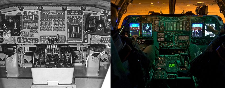
The composite photo gives a pretty good idea of how the cockpit of supersonic heavy bombers has evolved in about 50 years.
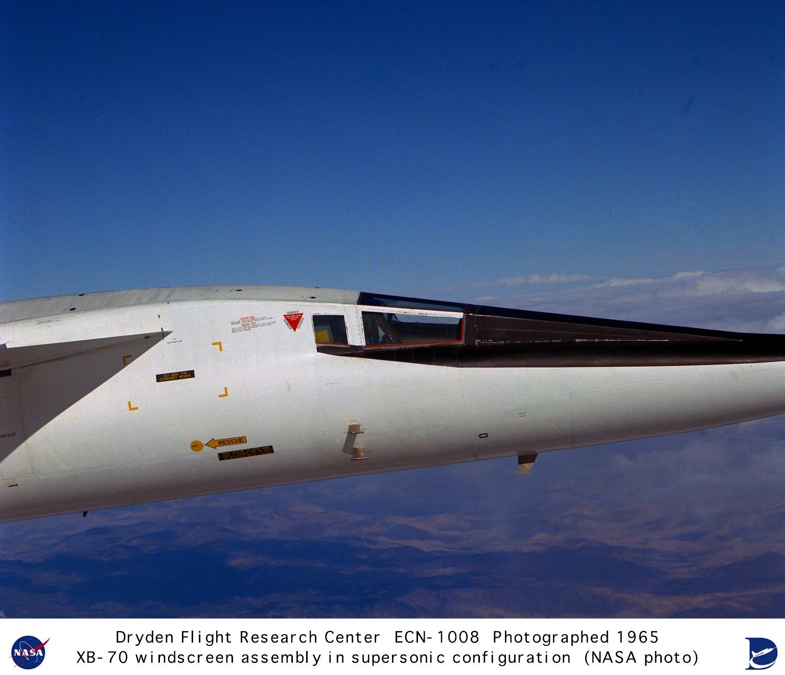
With a planned cruise speed of Mach 3 and operating altitude of 70,000 feet, the B-70 Valkyrie was to be the ultimate high-altitude, high-speed, deep-penetration manned strategic bomber designed in the 1950s. The 6-engine aircraft was expected to be immune to Soviet interceptor aircraft thanks to its stunning performance.
According to NASA:
“To achieve Mach 3 performance, the B-70 was designed to “ride” its own shock wave, much as a surfer rides an ocean wave. The resulting shape used a delta wing on a slab-sided fuselage that contained the six jet engines that powered the aircraft. The outer wing panels were hinged. During take off, landing, and subsonic flight, they remained in the horizontal position. This feature increased the amount of lift produced, improving the lift-to-drag ratio. Once the aircraft was supersonic, the wing panels would be hinged downward. Changing the position of the wing panels reduced the drag caused by the wingtips interacted with the inlet shock wave. The repositioned wingtips also reduced the area behind the airplane’s center of gravity, which reduced trim drag. The downturned outer panels also provided more vertical surface to improve directional stability at high Mach numbers. Attached to the delta was a long, thin forward fuselage. Behind the cockpit were two large canards, which acted as control surfaces.”
The aircraft was still under development when the future of the manned bomber became uncertain. Indeed, during the late 1950s and early 1960s, many believed that manned bombers had become obsolete, and the future wars would be fought by missiles. As a result, the Kennedy Administration ended plans to deploy the B-70 and the two XB-70 prototypes were under construction when the program was cancelled.
However, two experimental XB-70A prototypes were eventually built at North American Aviation and used by NASA test beds for an American supersonic transport (SST). NASA records show that XB-70A number 1 (62-001) made its first flight from Palmdale to Edwards Air Force Base, CA, on Sept. 21, 1964. Tests of the XB-70’s airworthiness occurred throughout 1964 and 1965 by North American and Air Force test pilots. The Flight Research Center prepared its instrument package.
“Although intended to cruise at Mach 3, the first XB-70 was found to have poor directional stability above Mach 2.5, and only made a single flight above Mach 3. Despite the problems, the early flights provided data on a number of issues facing SST designers. These included aircraft noise, operational problems, control system design, comparison of wind tunnel predictions with actual flight data, and high-altitude, clear-air turbulence.”
The second XB-70A (62-207) was built with an added 5 degrees of dihedral on the wings as suggested by the NASA Ames Research Center, Moffett Field, CA, wind-tunnel studies. This aircraft made its first flight on Jul. 17, 1965. “The changes resulted in much better handling, and the second XB-70 achieved Mach 3 for the first time on Jan. 3, 1966. The aircraft made a total of nine Mach 3 flights by June.

A joint agreement signed between NASA and the Air Force planned to use the second XB-70A prototype for high-speed research flights in support of the SST program. However, the plans went awry on June 8, 1966, when the second XB-70 collided with a civilian registered F-104N while flying in formation as part of a General Electric company publicity photo shoot outside the Edwards Air Force Base test range in the Mojave Desert, California, that involved an XB-70, a T-38 Talon, an F-4B Phantom II, an F-104N Starfighter and a YF-5A Freedom Fighter.
Toward the end of the photo shooting NASA registered F-104N Starfighter, piloted by famous test pilot Joe Walker, got too close to the right wing of the XB-70, collided, sheared off the twin vertical stabilizers of the big XB-70 and exploded as it cartwheeled behind the Valkyrie.
North American test pilot Al White ejected from the XB-70 in his escape capsule, but received serious injuries in the process. Co-pilot Maj. Carl Cross, who was making his first flight in the XB-70, was unable to eject and died in the crash.
Research activities continued with the first XB-70.
The first NASA XB-70 flight occurred on April 25, 1967, the last one was on Feb. 4, 1969 when the aircraft made a subsonic structural dynamics test and ferry flight from Edwards AFB to Wright-Patterson Air Force Base, OH, where the aircraft was put on display at the Air Force Museum after 83 test flights and 160 hours and 16 minutes, flight time. Indeed, despite research activity helped measuring its “structural response to turbulence; determine the aircraft’s handling qualities during landings; and investigate boundary layer noise, inlet performance, and structural dynamics, including fuselage bending and canard flight loads”, time had run out for the research program. NASA had reached an agreement with the Air Force to fly research missions with a pair of YF-12As and a “YF-12C,” which was actually an SR-71, that represented a far more advanced technology than that of the XB-70. Indeed, in all, the two XB-70Bs logged 1 hour and 48 minutes of Mach 3 flight time during their career, whilst a YF-12 could log this much Mach 3 time in a single flight.
Although the XB-70 program was cancelled, data collected during the Valkyrie test flights were used in other programs, including the B-1 bomber and the Soviet Tupolev Tu-144 SST program (via espionage).
We have recently found an interesting photo of the XB-70 #1 cockpit. The photo (courtesy of NASA) shows the complexity of the mid-1960s research aircraft especially if compared to a modern B-1 Lancer with the Integrated Battle Station upgrade.
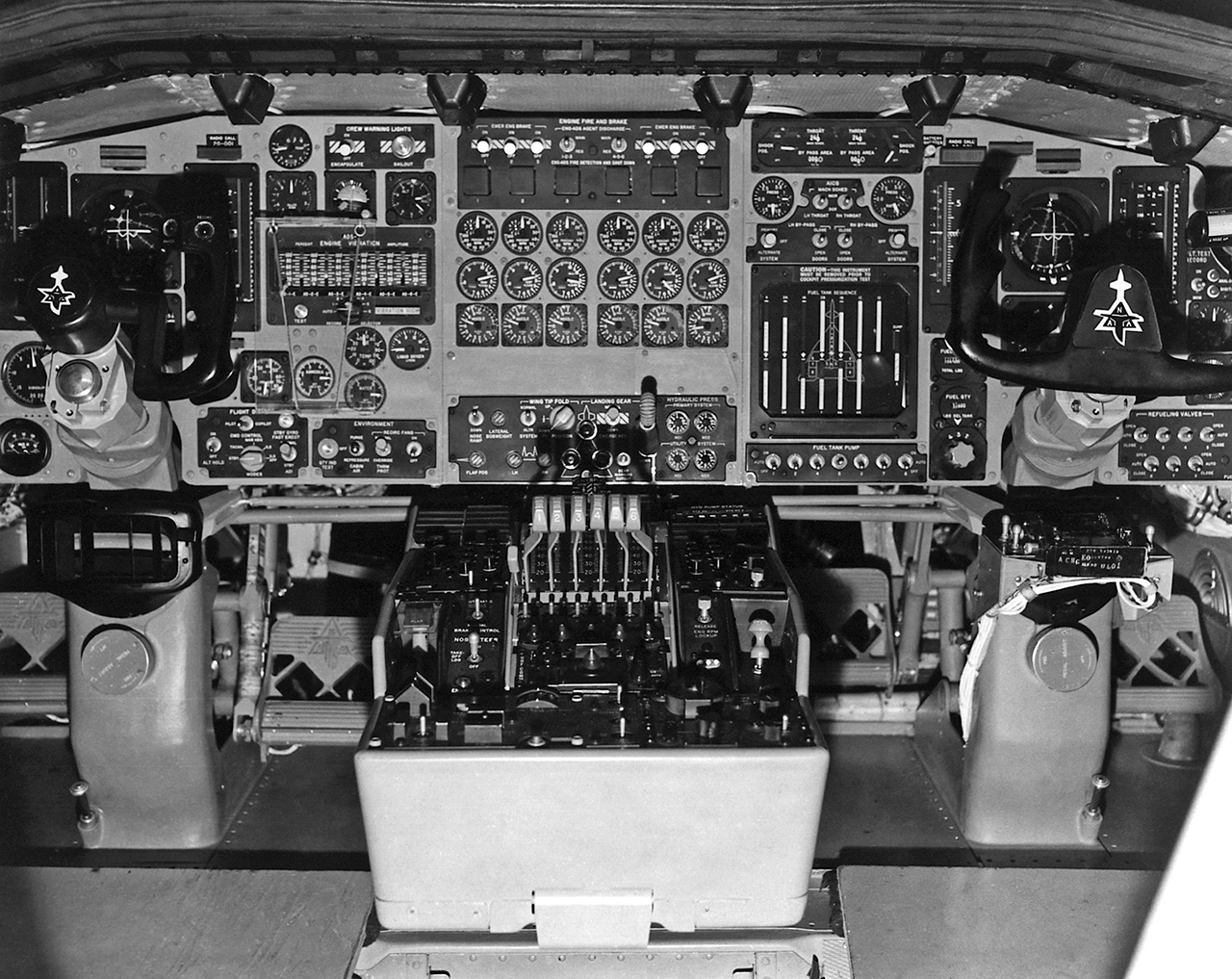
Here’s the official description of the cockpit:
On the left and right sides of the picture are the pilot’s and co-pilot’s control yokes. Forward of these, on the cockpit floor, are the rudder pedals with the NAA North American Aviation trademark. Between them is the center console. Visible are the six throttles for the XB-70’s jet engines. Above this is the center instrument panel. The bottom panel has the wing tip fold, landing gear, and flap controls, as well as the hydraulic pressure gages. In the center are three rows of engine gages. The top row are tachometers, the second are exhaust temperature gages, and the bottom row are exhaust nozzle position indicators. Above these are the engine fire and engine brake switches.
The instrument panels for the pilot left and co-pilot right differ somewhat. Both crewmen have an airspeed/Mach indicator, and altitude/vertical velocity indicator, an artificial horizon, and a heading indicator/compass directly in front of them.
The pilot’s flight instruments, from top to bottom, are total heat gage and crew warning lights; stand-by flight instruments side-slip, artificial horizon, and altitude; the engine vibration indicators; cabin altitude, ammonia, and water quantity gages, the electronic compartment air temperature gage, and the liquid oxygen quantity gage. At the bottom are the switches for the flight displays and environmental controls.
On the co-pilot’s panel, the top three rows are for the engine inlet controls. Below this is the fuel tank sequence indicator, which shows the amount of fuel in each tank. The bottom row consists of the fuel pump switches, which were used to shift fuel to maintain the proper center of gravity. Just to the right are the indicators for the total fuel top and the individual tanks bottom. Visible on the right edge of the photo are the refueling valves, while above these are switches for the flight data recording instruments.
Here below you can find a photo of the B-1 cockpit with the Integrated Battle Station upgrade which, beginning in 2014, gave the “Bone” new screens and updated avionics in both the cockpit and battle stations.
The IBS upgrade increased the situational awareness of the pilots by means of a Fully Integrated Data Link (FIDL), a Vertical Situation Display Upgrade (VSDU), and a Central Integrated System (CITS) upgrade.
Within the VSDU two unsupportable, monochrome pilot and co-pilot displays were replaced by four multifunctional color displays, that provide the pilots more situational awareness data, in a user-friendly format. The FIDL is a modern data link that allows the B-1 to interconnect and communicate in real-time, with other planes, ground stations, allied units. The CITS is an upgrade of the old LED display computers used by ground maintainers to identify and troubleshoot system failures.
If you click on the image you will find a cockpit with two control sticks, dominated by a mix of displays and moving maps (typical of glass cockpits) as well as analogue instruments: a hybrid cockpit, with common instruments such altimeter, ADI (Attitude Indicator) and Airspeed Indicator/Machmeter on the left hand side; flaps, slats and spoiler controls as well as TFR (Terrain Following Radar), fuel and engine instruments in the central part of the flight deck; and two large VSDUs that can be arranged at will to display the required information/digitized instrument, such as a moving map or a HSI (Horizontal Situation Indicator), on both sides.
Old-style monochrome displays that didn’t provide much processing nor display capabilities, were replaced by much larger color displays that can show significantly more information thus improving the situational awareness. With the IBS upgrade, data can be shown on any display of the aircraft with collaboration tools that enable the aircraft’s crew “to look at each other’s displays with a ghost cursor, so if one weapons system officer wants to see what someone else is looking at, he can see a ghost cursor over on his own display – this allows the crew to collaborate and ensures they’re all looking at the same thing,” said Dan Ruder, B-1 strategic development and advanced programs manager for Boeing, in a story published on Military Embedded Systems.

So, the instrument panel layout has remained more or less the same. The way information is displayed has significantly changed.


