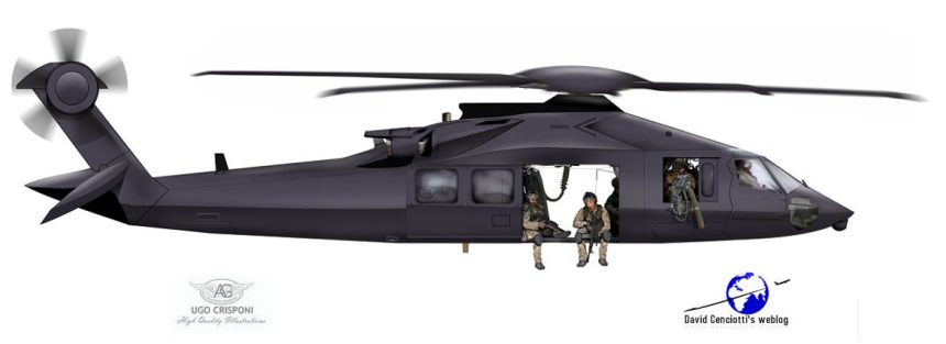
This is how the Stealth Black Hawk (dubbed also “Silent Hawk”) could look like based on the analysis of all the information available to date. It is sensibly different from the previous sketch; if you read below you’ll understand why.

After publishing the various famous sketches of the possible shape of the modified Black Hawk (dubbed “Stealth Black Hawk” or “Silent Hawk”), together with Ugo Crisponi I’ve continued studying pictures, suggestions, comments and all the information available about the mysterious helicopter that performed a crash landing during the Osama Bin Laden raid. While some hundred thousands readers all around the world, along with major media worlwide, much appreciated our work, others argued that we were giving bad guys some valuable information about a “black project”. Actually, the sketches were based on my initial analysis of the publicly available pictures, that Ugo was able, through a series of attempts, to “translate” into a realistic shape. So, what we did could be done by anybody willing to spend some time studying images and thinking to all the possible modification that could make a Black Hawk, if not stealth, more silent.
Furthermore, a far more in-depth study that could be used to project a Low Observability UH-60 is already in the Public Domain and freely available on an official US military website. It was issued in 1978 by Sikorsky Aircraft Division for the US Army Research and Technology Laboratories and it is titled: “STRUCTURAL CONCEPTS AND AERODYNAMIC ANALYSIS FOR LOW RADAR CROSS SECTION (LRCS) FUSELAGE CONFIGURATIONS”. It shows that first attempts to give the UH-60 some stealth capabilities dates back to 33 years ago. Although I can’t expect the fuselage concepts for low radar cross section aircraft configurations designed at the end of the ’70s still apply today, the basic concept around them could be still useful to imagine a few modifications to the Stealth Black Hawk profile as I initially thought it.
Noteworthy, the shape suggested in 1978 document reminds that of an F-117 rather than that of a more modern stealth, like an F-22. This is consistent with the article published on Army Times titled “Mission helo was secret stealth Black Hawk” according to which the helo has “hard edges, sort of like an … F-117, you know how they have those distinctive edges and angles — that’s what they had on this one”.
Here below, you can read some excerpts of the above mentioned public document that I used with Ugo Crisponi of Aviation Graphic to review the sketch.
Three fuselage configurations for low radar cross sections were developed by the Applied Technology Laboratory. […] The main rotor pylon fairings and tail surfaces aft of a tail fold hinge for each configuration were the same as those for the baseline UH60A. In the initial portion of this study, the weight and costs (percent of total) were developed for sections of the baseline UH60A fuselage. […] Structural concepts were developed which could be applied to each configuration using conventional materials. An assessment of safety, fail-safety, and maintainability for each configuration was performed. The change in structural weight and the percentage change in cost for each configuration using the concepts developed were compared to those of the baseline. One concept was selected and applied to the three configurations.
Having selected the structural concept with the lowest weight change and percentage cost change for the three fuselage configurations, the effect on weight and costs using advanced materials was developed and applied to the three configurations. To evaluate the impact of the results of the fuselage study, design attributes of six helicopters were developed using a Helicopter Design Model (HDM) computer program.
Three low radar cross section fuselage configurations for this study were developed by the Applied Technology Laboratory. The first configuration slightly modified the nose section from the baseline configuration; the second configuration changed the fuselage shape along the lines of a truncated triangular prism; the third extended canted flat side shaping throughout the fuselage. The tail surfaces and main rotor pylon fairing were the same as those of the baseline UH60A.
CONFIGURATION 1
This configuration alters the baseline fuselage forward of the mid-cabin section (the cockpit). Although this configuration is different from the baseline, the internal structure must be compatible with the forward cabin to avoid a heavy joining structure. The overall length is slightly increased due to this configuration.


CONFIGURATION 2
This configuration is basically a trapezoidal cross section airframe having sides canted inward 30° and made up of flat exterior structural panels. This configuration is wider at the bottom of the fuselage and narrower at the top of the fuselage than the baseline. This configuration is slightly longer than the baseline UH60A, and its overall height is slightly larger than the baseline. The increased length, width, and height of Configuration 2 does not allow an aircraft of this size to meet the air transportability requirements of the baseline. The narrow upper fuselage causes the pilot and copilot seats to be spaced closer to each other, and shoulder room in the main cabin is decreased. The main cabin floor is approximately 6 inches higher than the baseline from the ground. The increased floor-to-ground height causes difficulties for combat troops to enter or leave the aircraft quickly. Minor modifications of the mold lines for the transition and tail-cone sections were made to properly house the tail rotor shaft of the baseline UH60A.


CONFIGURATION 3
This configuration is basically a flat side cross section airframe having sides canted inward 50 and is tapered in width from a narrow cockpit section to a transition section as wide as the baseline UH60A. The tail-cone is a rectangular section which is narrower than the baseline. The narrow cockpit causes the pilot and copilot seats to be spaced closer to each other; space for four-across seating in the main cabin is decreased. The cockpit and main cabin floors are at the same height from the ground as the baseline. The slope of the windshields may cause problems of visibility for the flight crew. Minor modifications of the mold lines for the transition and tail-cone sections were made to properly house the tail rotor shaft of the baseline UH60A.


ADVANCED MATERIAL APPLICATION
Advanced composite materials can be used in the construction of the three fuselage shapes considered in this study. Studies, have shown that the use of composite materials can reduce both fuselage weight and cost. The fuselages of this study are relatively lightly loaded compared to fixed-wing aircraft. To efficiently use advanced materials in the fuselages, very light composite skins are used in the post-buckled stress state. […]
CONCLUSIONS
Structural concepts developed for the three LECS configurations showed that extensive reshaping, as exemplified by Configuration 2, would increase fuselage weight from that of the baseline UH-60A fuselage by 223 pounds and cost by 3.65 percent. When advanced materials were used Configuration 2 decreased
from the baseline fuselage weight and cost by 116 pounds and 3.98 percent respectivdly. Total aircraft performance capability was degraded primarily by drag effects. The aerodynamic analysis indicated that Configuration 2 would have a vertic climb rate at 15 percent of the baseline. Weight, cost, and performance penalties were less in Configurations 3 and 1 respectively.
Based on the results of this study, the following conclusions are made:
1. The use of advanced materials can result in both weight and cost savings over the baseline fuselage, even with the most severe change in LRCS configurations presented.
2. Without the use of advanced materials, the LRCS Configurations 2 and 3 significantly increase both weight and cost of the total aircraft compared to the baseline UH60A.
3. Minor changes to the nose section of Configuration 1 result in negligible fuselage difference to the weight and cost of the fuselage.
4. Consideration of the total aircraft attributes show that vertical drag penalties appear to be of greater magnitude than the structural weight changes involved with the fuselages of Configurations 2 and 3.
Even with the use of advanced materials, the vertical drag penalty exceeds any weight savings.


The sketch was revised to take the document into consideration (without forgetting it was issued at the end of the ’70s). Even the main rotor was redesigned to make its head slightly larger (with a noise reduction cover sheltering the motion-control technology used to input low-frequency variations of rotor blade pitch-angle, as tested by NASA) .
One last thing worth a mention.
In the aftermath of the crash landing, on May 5, Jon Nowinski, an investigative reporter and founder of the Smoking Gun Research Agency (www.sgra.org) sent me an email to let me know that:
[… ] over the last few days there has been an increased number of late-night helicopter flights to the Sikorsky plant. While that doesn’t entirely stand out as odd, it is interesting to note that normally these flights are related to testing aircraft, as well as consistant with what happens when a Sikorsky helo goes down in military action. After an accident like that, military investigators and officials frequently come out to the Sikorsky plan for a debriefing during which they review the operation